Posts

Image
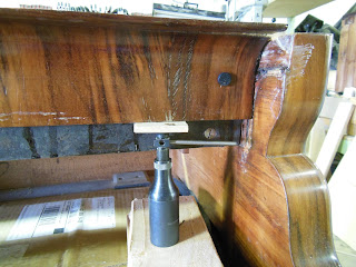
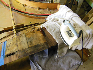
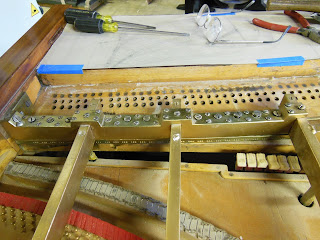
The pin-block completely revealed, with the central strut removed, as well. The pin-block and shelf can now be removed. As I mentioned before, the shelf is sitting in a tapered groove, there is about an inch and a half of material in front of this groove, that is keeping the block in. I know that it is possible to disassemble the front of the case to gain access to the groove, but this seems to me, more likely to result in damage, than the method I am using below. In the above photo I have removed the veneer, first from the front of the arm, and then, the thicker piece, from the inside. Although I think this is the better way, I would just like to say, that it really hurt me to remove this small block of wood. Below; I thought that as the groove, or dado (groove is actually correct) was tapered in my favor, that removing the shelf would be relatively easy, once I got it going. I was wrong. The shelf was very badly warped in the groove, and I had to work hard, the whole way ou...
Image
With the iron bar removed, we can see the three layers of the pin-block stretcher. The lowest level is the shelf. The shelf has a layer of decorative veneer on both sides, which on both top and bottom, extend all the way to the front. The species of this veneer is (Platanus hybrida) European Plane. The grain runs front to back as with cross-banding. the next layer is the pin-block proper, and finally the stretcher. Above  a piece of the stretcher removed revealing the pin-block. Two wood screws pierce the block and penetrate into the lower shelf. The dark line is a layer of dark veneer under the pin-block face. The grain of the face veneer runs front to back. On the left, The central plate strut and its key. See below. The strut is fastened by the one one wood screw, pictured, but is not attached to the key, which sits in a shallow mortise. The gouge running diagonally down from left to right, is the remains of an exploratory hole drilled by an earlier explorer. The r...
Image
Here is a front view of the stretcher fascia, being slowly jacked up and out of the instrument. Behind it you can see the iron bar, which is actually quite large and heavy, and is secured by a somewhat motley assortment of screws, in an odd arrangement. Above, the iron bar revealed. This is sort of like putting the pin-block flange, behind the pin-block. Erard was not the only one to do this. the remaining plate strut projects all the way through the stretcher and contacts the bar, without actually being attached to it. A closeup of one end of the iron bar, showing also the groove into which the spline of the fascia fit. This groove is about 1/8" deep, and is cut just through the veneer, which is very thick in this area. The name stamped on the back of the bar (CHATILLON.SS)
Image
Now the veneer can start to come off the top of the stretcher assembly. I used to be terribly afraid of this, but the trick is not to use a hot iron. Instead set the iron on the lowest setting, so that the temperature gradient is not too great, and the glue has a chance to get warm before outside burns. I use a clean wet, but not sopping, towel between the iron and the veneer, and, of course, the veneer has been stripped of finish. If you want to preserve the finish this is not the method. Plenty of patience is required, which with me, is always in short supply. Use a spray bottle of water and keep the towel wet. When the veneer begins to loosen work a thin, but not sharp blade underneath. The backs of the removed pieces are washed with hot water to remove any remaining glue, and then packed between clean paper toweling and put under pressure. Now we can see that the top of the stretcher is made of several pieces, with small slips of veneer between them, and that one of t...
Image
Here is one of the two fellows I mentioned earlier. Each of these was cast in two parts out of Bronze, and machined. One has to admire the level of effort that went into making and installing them, all for naught . The agraffes, also pictured here, are all too badly damaged to be reused. They were all drilled out, in place, to accommodate  larger modern wire. All the string lengths, the strike line spacing, and the string heights were recorded, before the instrument was unstrung. For those of you more fastidious than me, I did keep the wire and the pins, although they are modern, just to have a record, and to know the string tension on the instrument when it first arrived.
Image
But wait, I have forgotten about the Barre Harmonique, an important invention of Erard, and precursor of the modern Capo-bar. This had to be removed before the plate struts. Let's examine this bar more closely. Unlike the modern Capo, this bar is made in two parts. The lower part, which is the actual termination piece, has the cross section of an L lying on its back. The short vertical leg is pierced to form the termination, and the long leg is screwed to the shelf. The upper part is a massive block of Brass machined to fit over the plate struts. This block is secured using three classes of screws. see below, The large screws that run down the center of the bar, are wood screws that pierce the termination piece and thread into the shelf. The center screws above the struts are machine screws that thread into the struts. The remaining screws along the edges of the bar, are machine threaded into the upper bar itself, and bear against the top of the termination piece. Why the t...
Image
Before I can start to remove the pin-block, I would like to remove all the plate struts, except the center strut which is built into the stretcher. To do this I must cut apart the welded-in cross bars which are not original to this piano. In the photo above, the sound-board is protected with cardboard, and thin plywood before the bars are cut apart with a Sawzall. This is brutal work, and thankfully takes only a few minutes. The plate struts are screwed into the piano. On the hitch-pin panel they rest on, and are screwed to steel stanchions (stand-offs). These small blocks of metal form the head of a bolt which passes through the hitch-pin panel and into the inner rim. In the front there is a similar arrangement, with small metal blocks, whose lower part forms a machine screw that passes through the shelf, and is secured from below with a round nut. Between these are a series of nose, or pillar bolts, that pierce the sound-board, and likewise through the strut, then being ret...